
수 표현
4'blll1 // 4 비트 2 진수
12'habc //12비트 16진수
16'd255 //16 비트 10진수

-6'd3 // 3이 2의 보수로써 음수
- 4-bit binary number: 1111
- 12-bit hexadecimal number: habc
- 16-bit decimal number: 255
음수는 앞에 -가 붙는다. // two's complement 사용.

| #of Bits : binary로 표현 시 몇 bit | Stored : binary로 표현 했을 때 |
| Invalid : 5는 binary가 될 수 없다 . . . | Unsized : 몇 bit인지 표현되어있지 않는다. |
논리값
| 논리값 수준 | 하드웨어 회로에서의 상태 |
| 0 | 논리적 0, 거짓상태 |
| 1 | 논리적 1, 참 상태 |
| x | 알 수 없는 논리 값 |
| z | 하이 임피던스, 플로팅 상태 |
Net
wire
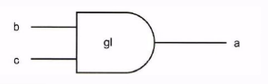
wire a; //위의 회로에서 Net a를 정의
wire b,c; //위의 회로에서 Net b,c를 정의
wire d=1'b0 // Net d는 논리값 0으로 선언
Register (레지스터)
wire과 다르게 어떠한 net이 레지스터에 연결되어 있어 데이터가 저장되어있음.
데이터를 저장해 둘 수 있는 변수. 기본적으로 1 bit이다.
reg reset; // 값을 가질 수 있는 변수 reset 정의 reset이라는 변수가 reg에 연결되어있음.
integer i; //32-bit 부호 있는 값.
벡터형 wire와 reg
wire a; //a는 1bit
wire [7:0] bus; //0~7 -> 8bit짜리 bus 변수
wire [31:0] busA, busB, busC; //32bit 짜리 3개의 bus
reg clock;  //register에 연결된 clock 변수.
reg [0:40] virtural_addr; //41 bit 짜리 레지스터에 연결되어 있는 변수 virtural_addr;
일부를 골라 쓸 수 있다.
System task
실제 회로는 아니며 컴파일러가 지원하는 보조함수들로 디버깅에 사용한다.
$display()
: printf로 생각하면 된다.
$display("Hello Verilog World");
//출력 : Hello Verilog World .

$display( $time);
//현재 시뮬레이션 시간을 출력한다.

reg[0:40] virtual addr;
$display("At time %d virtual address is %h",$time, virtual_addr);
//시간과 41bit virtual address의 값 1fe000001c 를 출력한다.

reg[4:0] port_id;
$display("ID of the port is %b",port_id);
//port id 값 5를 2진수로 출력.
//출력 : ID of the port is 00101
$는 변수 앞에 붙지 않음을 유의하자.
%b 는 2진수 출력, %d는 10진수 출력 , %h는 hexa decimal을 출력한다.
Module
| module module_name(port_list); //Semicolon 유의 port 선언 reg 선언 wire 선언 parameter 선언 하위 모듈 호출 always, initial 문 function, stask 정의문 assign 문 function, taks 호출문 enmodule //No Semicolon |
//half adder은 input이 a,b이고 output이 cout, sum인 adder
module half_add1 (a,b,sum,cout); //Module의 이름과 필요한 Ports를 인수로 적는다
	inpus a,b;
	output sum, cout; //port mode 선언

	wire cout_bar; //내부신호의 선언. Port로 선언된 것은 일단 wire이다.

	xor(sum,a,b); //output이 sum, input a,b
	nand(cout_bar,a,b); //output이 cout_bar, input이 a,b
	not(bout,cout_bar); //output이 bout, input이 a,b

endmodule
sum은 a,b를 xor한 값이다.
cout은 a,b를 nand gate를 지난 후 not gate를 지난 값이다. 따라서 nand 와 not gate 사이의 값을 임의로 cout_bar로 정의한다.
module fulladd4(sum,c_out,a,b,c_in); //4bit 짜리 FULL ADDER
output[3:0] sum; //sum은 4bit
output c_out; //cout은 1 bit
input [3:0] a,b;
input c_in;
...
<모듈 내용>
...
endmodule

//4bit full adder을 완성 했을때..
Module Top;
//연결 변수 선언
	reg[3:0] A,B;
	reg C_IN;
	wire[3:0] SUM;
	wire C_OUT;

//fa_ordered 라는 fulladd4의 파생
//신호가 위치에 의해 연결
fulladd4 fa_ordered(SUM,C_OUT, A,B,CIN);
//fulladd4를 불러옴 !! fulladd4를 불러와 sub name을 만들어줘야함.
//order을 맞춰줘야함(인수를 맞춰줘야함)
..
<스티뮬러스>
...
endmodule

//모듈 fa_byname의 파생과 이름에 의한 신호 연결
fulladee4_fa_byname(.c out(C OUT), .sum(SUM), .b(B) , .c_in(C_IN),.a(A),);
// .을 쓸 경우 순서를 신경 쓰지 않아도 된다.
// . 과 순서를 모두 맞춰 실수하지 않도록 하는게 좋다.
모델링하기 : GATE-LEVEL

mux4

4개가 input, 2개의 select (총 6개)
1개의 output
module mux4_to_1(out,i0,i1,i2,i3,s1,s0);
//input, output 다이어그램으로부터 포트를 선언.
	output out;
	input i0,i1,i2,i3;
	input s1,s0;

//내부 wire 선언.
	wire y0,y1,y2,y3;
	wire s1n,s0n;

//not 게이트 파생, s1n, s0n 신호 생성
	not(s1n,s1);
	not(s0n.s0);

//3-input AND 게이트 파생
	and(y0,i0,i1,s1n,s0n);
	and(y1,i0,i1,s1n,s0n)
	and(y2,i0,i1,s1n,s0n)
	and(y3,i0,i1,s1n,s0n)

//4개의 입력을 갖는 OR 게이트 파생
	or(out,y0,y1,y2,y3);

endmodule
Full Adder

modul FullAdder(sum,c_out,a,b,c_in);

//IO포트 선언
	output sum,c_out;
	input a,b,c_in;

//내부
	wire s1,c1,c2;

//pritive logic gate 파생
	xor(s1,a,b);
	and(c1,a,b);

	xor(sum,s1,c_in);
	and(c2,s1,c_in);

	xor(c_out,c2,s1);

endmodule
4-Bit Full Adder

module fulladder4(sum,c_out,a,b,c_in);
//c_out, c_in은 1bit, 나머지는 4 bit

//IO 포트 선언
	output [3:0] sum;
	output c_out;
	input [3:0) a,b;
	input c_in;

//내부 net
//carry를 net으로 설정
	wire c1,c2,c3;

//4개의 1bit 전가산기 파생
//fa0,fa1,fa2,fa3 과 같은 sub name을 써야한다.
	fulladd fa0(sum[0],c1,a[0],b[0],c_in);
	fulladd fa1(sum[1],c2,a[1],b[1],c_1);
	fulladd fa2(sum[2],c3,a[2],b[2],c_2);
	fulladd fa3(sum[3].c4,a[3],b[3],c_out);

endmodule
data flow 모델링
게이트 대신 연산자와 할당을 사용한다. 할당에는 반드시 앞에 assign을 넣어야 한다.
and(out,i1,i2)
assign out = i1 & i2;input i1과 i2를 and gate 연산을 하여 out을 할당한다.
xor
assign addr[15:0] = addr1_bits[15:0] ^ addr2_bits[15:0];not
~
레지스터에 연산을 할 경우
integer count, final_count;
final_cout=count+1;

real a,b,c;
c=a-b;

reg[15:0] reg1,reg2;
reg[3:0] reg_out;
reg_out=[reg1[3:0] ^ reg2[3:0] //reg1과 reg2는 부분 선택 레지스터 피연산자이다.
reg1,2는 15bit 이다. reg_out,에서 reg1,2는 3bit씩만 뽑아와 사용한다.
연산결과를 reg에 저장하기
조건연산자
if,else와 비슷 하다.
//2:1 mux 기능적 모델
assign out=control ? in1: in0;
contorl==true라면 out은 in1, 아니라면 in0이다.
Data flow modeling
half_adder
| a | b | cout | sum |
| 0 | 0 | 0 | 0 |
| 0 | 1 | 0 | 1 |
| 1 | 0 | 0 | 1 |
| 1 | 1 | 1 | 0 |
module half_adder2(a,b,sum,cout);
	input a,b;
	soutput sum, cout;

	assign cout=a&b;
	assign sum=a^b;

endmodule
module half_add1(a,b,sum,cout);
input a,b;
output sum,cout;
wire cout_bar;
xor(sum,a,b);
nand(cout,bar,a,b);
not(cout,cout_bar);
endmodule∴cout_bar과 같은 과정(intenal wire)을 거치지 않고 연산자로 바로 설계할 수 있다.
Behavioral 모델링
회로라는 느낌이 없이 알고리즘적으로 모델링 가능하다.
always 구문
변화가 생길때 항상 쓰인다.
awlays@ ( );
ex) 2bit mux가 있다고 생각해보자.
module mux2b-if(in0,in1,sel,out);
	input [1:0] in0, in1;
	input sel;
	output [1:0] out;
	reg [1:0] out;

//시뮬레이션이 시작하면 수행시작
	always @(sel or in0 or in1) begin
	if(sel ==0){out = in0};
	else{out=in1};
	end
//end까지 모든 동작 수행을 다 했다면 처음으로 돌아가 반복을 수행
//항상 수행하고있다.
endmodule
sel이 0라면 in0가 out이 되고 아니라면 in1로 간다. 즉, always안의 변수들이 바뀌면 바뀐다. int1,in0, sel이 바뀌면 always가 다시 실행 되며 output이 바뀐다.
mux 2_to 1
if/else
module mux_2_to_1(a,b,out,outbar,sel);
	input a,b,sel;
	output out,outbar;
	reg out;

	always @ (a or b or sel)	begin
		if(sel) out=a;
		else out=b;
	end

	assign outbar=~out;

endmodule
case
module mux_2_to_1(a,b,out,oubar, sel);
	input a,b, sel;
	output out,outbar;
	reg out;

	always@ a or b or sel)	begin
		case(sel)
			1'b1: out=a; sel이 1bit짜리 1이라면 out=a
			1'b0:out=b;
		endcase
	end

	assign outbar= ~out;

endmodule
Testbench 모델링
테스트벤치 모듈은 HDL 모델을 시뮬레이션 하기 위한 Verilog 모듈이다.
시뮬레이션입력(stimulus)를 DUT에 작성하고 시뮬레이션 대상이 되는 모듈을 적고 reponse를 관찰하게 된다.
initial 구문
전체 시뮬레이션에서 한번만 수행할 내용들 (초기화, 모니터링 , Test용 으로만 할것)
reg x,y;

Initial begin
x=1'b0;
y=1'b1;

end
Testbench example
TEST_FIX
module test_fix();
reg A,B,C;
circuit c1(A,B,C,Out);

initial begin
A=0; B=1; C=0;
#50 A=1;  //50초 뒤에는 A=1로 바뀌고 나머지는 유지
#50 A=1; C=1; //그 다음 50초 뒤에 ..
#50      C=0;
#50 $finish;

end
endmodule
유의) 하드웨어 언어와 소프트웨어 언어는 다르다. 되도록 이중 alway문은 피해야 한다.
또한 alway 블락 안에 initial을 쓸 수 없으며 반대로 initial 문 안에 alway또한 사용 불가능하다.
'학사_공부 정리 > 디지털논리회로' 카테고리의 다른 글
| [Verilog] 베릴로그 기본 (0) | 2022.12.09 |
|---|